Mechanical Aids to Calculation

Mechanical Aids to Calculation

The following are extracts from a paper presented to the Institution of Engineers Australia on Thursday May 13th 1920 by George Alfred Julius – Member. It was published by the Sydney Division of the Institution of Engineers Australia.

Summary

Brief historical record is made of calculating machines in use many centuries ago, and of the great advance in rapid calculations by the invention of logarithms. During the past fifty years various mechanical “arithmetical” machines and “instruments” of calculation have been perfected, and are largely used in porno work, and by those engaged in the preparation of mathematical tables, insurance records, census returns, and similar work. All these machines, however, have been designed for operation and control by a single operator. By means of diagrammatic sketches the essential principles and development of such machines are described.

Of recent years, however, a need has arisen for an adding machine which will pick up and add the records passed on to it by a number of independent operators. Particular applications of this requirement are found in railway ticket printing and issuing, in the recording of sales in large departmental stores, and in racecourse totalisator practice.

The paper describes the development of a machine that has been built in Australia capable of meeting such requirements and of recording records received from as many as 1000 independent operators, and at speeds as high as 4000 a second. These machines are capable of both printing and issuing tickets, and at the same time recording the issue of such tickets when issued in great numbers and simultaneously by a number of selling machines.

The machines are equipped with safety gear of various kinds to prevent the issue of tickets without recording same, and generally to ensure absolutely accurate results.

File:19th-and-early-20th-centuries-calculating-machines.jpg ...

Extract 1

It has been suggested to the writer that members might be interested in a brief description of a mechanical “adding machine,” which has been developed and built in Australia, and which differs entirely in principle and in detail from any other form of mechanical calculator.

Extract 2

In all the adding machines so far described, the mechanism is such that only one addition can be made at one time; in other words, the machines are not capable of allowing for the simultaneous adding of a number of different amounts. Just as with the typewriter, the adding machines have all been designed for control and operation by a single operator.

Of recent years, however, another problem has come forward to meet which it has been necessary to devise an adding machine that can add numbers transmitted to it from several operators, even if those operators all transmit their records at precisely the same instant of time. In such a case the machine has to “jump the total.”

The requirements may be made more clear by taking a particular case.

On various racecourses throughout the world the law permits the use of a machine known as the totalisator. This is primarily a system of machine betting. Tickets are sold from a number of selling booths on the horses entered for a race, and the total number of tickets sold on each of these horses, and also the grand total of all the tickets sold on the race, have to be re- corded. The ratio between the grand total of all such investments and of the total investments on any particular horse is a measure of the return which an investor on that horse will receive if the horse wins the race.

The period during which tickets are sold on any one race is usually about half an hour, and during that time the total number of tickets issued on the largest racecourse may reach 1,000,000, which involves an average speed of approximately 33,000 tickets per minute. Actually, the issue is never evenly divided over the whole of the available time, it being almost invariably slower at first and correspondingly faster at the last. Tickets of different values also are generally sold; thus the ticket of lowest value may be 10s., the next 1 pound, then 5 pounds, 10 pounds, and so on, up to even 1,000 pounds.

The tickets

The sales have to be recorded to show the equivalent number of tickets of the lowest denomination on each horse and on the grand total. Each 10s. ticket must therefore register one, each 1 pound ticket two, each 5 pound ticket ten, and so on, up to the 1,000 pound ticket, which must register as two thousand, as it is equivalent to two thousand 10s. tickets.

The machine to be installed therefore, must automatically record from instant to instant the total sales on each horse, and the grand total of all sales, and must display these figures in such a way that they may be easily legible to the public. This last requirement necessitates the use of very large counters or numerators, as the figures require to be legible from a distance of at least 200 feet.

This latter condition necessitates the use of counter wheels of large diameter, even as much as 2 feet, and as the speeds at which they are required to revolve is sometimes great, and the inertia, however lightly they may be constructed, considerable, they cannot therefore be started or stopped suddenly. Further, also, in such installations it is necessary to locate many of the ticket-selling booths at a considerable distance from the adding machine, which necessitates the use of electric power for the transmission of the records from the selling machines to the recording machine.Computers of the Future: Intelligent Machines and Virtual Reality ...

Difficulty arises but won’t stop us

Here, again, difficulties arise, as the first requirement of a totalisator is absolute accuracy, and the use of electric transmission obviously introduces a possible weakness which has to be guarded against Thus, an electric cable may break, insulation may fail, magnet coils may burn out or short or there may even be a complete interruption in the supply of electric power to the machine. A complete system of safety gear has therefore to be introduced, which will only permit of the issue of a ticket at any booth on any horse if the electric connection between that selling machine and that horse is in order, and electric power available.

This may be more briefly expressed by saying that the whole installation must be so arranged that no ticket can possibly be issued without its issue being correctly recorded and vice versa, that no “record” can be transmitted and recorded without the corresponding issue of a ticket.

One more factor also is of importance. The whole equipment has frequently to be worked at very high pressure during selling operations, and the liability of faulty operation of the ticket-selling machines is thus greatly increased. The design of these equipments has, therefore to be such as to make them as nearly ” fool proof ” as possible.

Specific conditions

The foregoing will have made clear the very peculiar and somewhat exacting conditions that have to be met in order to ensure a successful solution of’ the problem.

The first and most essential factor is the obtaining of a mechanism which will add the records received from a number of independent operators. This has been done in two ways. The first method, which has met with a certain measure of success in small equipments, depends upon the release of a marble or steel ball whenever a ticket is issued.

These marbles are held in magazines, and as released they gravitate to one or other of a group of counters, and operate the counters by reason of their weight or through some trip mechanism. After passing through the particular horse counter, they are all elevated by conveyor to again gravitate to, and operate the grand total counter. Thus, if twenty sellers at the same instant each issue a 10s. ticket on one horse, twenty marbles are released, one from each of twenty magazines and these all gravitate to operate the horse counter.

Mechanical calculator - Wikipedia
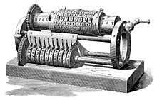
After completing this work the twenty marbles are elevated by conveyor to then run through and operate the grand total counter. If a 1 pound ticket is sold two marbles have to be released, and similarly ten for a 5 pound ticket, and so on. There are obvious limitations to this system, but as the originator of a rival system, the writer does not feel justified in making further reference to them. The other system of “collective adding,” as it may be called, depends primarily upon the use of a group of super-imposed epicyclic gears. Such a group is shown diagrammatically in Figure 8.

Aids to Calculation

Aids to Calculation

In describing this gear, reference will only be made to the process of “addition,” but it is obvious that the gear is equally applicable to subtraction. The gear, as shown, is arranged to receive and add records from six operators, and to show the total upon the total wheel marked “T,” by rolling this total wheel towards the left, as shown by the arrow.

For convenience let it be assumed that a movement of the wheel “T” of 1/4 inch to the left represents the issue of one ticket. The six selling machines are connected to the wheels “A,” “B,” “C,” and “D,” and to the racks “E” and “F” respectively. The double racks “P,” “Q,” “R,” and “S” are not connected to selling machines, and are merely portion of the adding mechanism.

Suppose the wheel “A” to be connected to a 10s. issuing machine, and to be so arranged that the issue of each 10s. ticket causes it to roll 1/4 inch to the left, as shown by the arrow. If the operator of the selling machine connected to this wheel “A” then issues a ticket, the wheel will travel 1/4 inch to the left, rolling upon the momentarily fixed rack “R,” and thereby moving the rack “P” 1/2 inch to the left.

The teeth on the upper face of the rack “P” will then obviously cause the total wheel “T” to roll along the momentarily fixed rack ” Q,” and thus to travel, as a whole, 1/4 inch to the left. It is seen, therefore, that the movement of the wheel “A” 1/4 inch to the left will of itself cause the total wheel ” T” to move 1/4 inch in the same direction.

Extract 3

It is obvious, however that the gear as shown in diagram No. 8 could not be used, because the racks would have to be of impracticable length, and in practice the racks are replaced by bevel wheel. The various records are then made by the rotation of the wheels A, B, C, D, and hence T about their axes, instead of by the lateral translation of these axes.

This arrangement is shown in Figure 9 (the corresponding parts in the arrangement shown in Figures 7 and 8 being “lettered” the same), and its operation should readily be followed, it being merely necessary to change the motion of translation of the gears shown Figure 8 to one of rotation of the gears shown on Figure 9.

At this point a number of difficulties arise. Firstly, it would be manifestly impossible to accurately rotate these gears by means of the impulses received from the ticket-selling machines. Not only would the power required be excessive and the mechanism very complicated, but the “backlash” in a train of gears such as that described would give rise to endless inaccuracies. “Power” has therefore to be applied to move the gears, and to be so arranged that the issue of tickets on the various ticket issuers controls the extent of the movement.

Brunsviga calculating machine | Science Museum Group Collection

Extract 4

The epicyclic gears, however, must obviously respond instantly to the records transmitted through them. Thus, if fifty clerks simultaneously issue tickets on the same horse, the records of those sales must instantly be picked up by the epicyclic gears, and as the large counter wheels cannot instantly respond to this demand some form of “storage” gear has to be introduced between the epicyclic gears and the counters to “store” up the records until the counters can he brought up to the necessary speed to record the sales.

But this alone would not be sufficient, because if a form of storage gear was put in to merely allow the counter to get up to speed, then if at one instant tickets were passing at the rate of, say, 2,000 a minute on a horse, and at the next instant the issue of tickets ceased, the counters would work up to their speed of 2,000 a minute, and then required to stop dead when running at top speed.

Such an arrangement would be obviously impracticable, and the goal has therefore to be so designed as to allow of, firstly, the instantaneous response of the epicyclic gear to the demands made upon it; secondly, the storage of these impulses during such time as the speed of the counters is being brought up to meet the requirements; and, thirdly, the gradual slowing down of the counter as it overtakes the registration of the stored-up records.

In other words, the mechanism that stores up the records has to control a variable speed gear, which will as required gradually speed up or gradually retard the counters, and so avoid all shock to the mechanism.

Extract 5

In the original designs the issue of all tickets of every denomination whether 10s, 1 pound, 5 pounds, or ten pounds, were transmitted to the unit wheel of the counters or numerators. This, however necessitated a very high speed of operation for the unit wheel, because although each unit bet only required one-tenth of a revolution of this wheel, each ten pound ticket required two complete revolutions and in a machine of this type and of relatively small capacity, the speed of the unit wheel frequently reached speeds as high as 200 revolutions a minute.

As it was obvious also that tickets of a denomination higher than ten pounds would be required, and even possibly as high as 1000 pounds it was apparent that the practice of passing all registrations through the unit wheel would have to be abandoned.

In the latest type, therefore, only the 10s. and one pound registrations pass through the unit wheel. The 5 pound and 10 pound registrations are passed direct to the 10’s wheels, the 50 pound and 100 pound direct to the 100’s wheel, and so on. This, again, required some special design, because the 10’s wheel had to record not only the 10’s carried forward from the additions of records from the 10s. and 1 pound issuers, but also had to register the direct issue of 5 pound and 10 pound tickets, and similarly for the 100’s wheel.

It will also be remembered that in describing mechanical systems of numeration, it was pointed out that the only satisfactory form of counter was one in which the various wheels moved instantaneously to the required position. Thus the 10’s wheel would be required to move one division at the instant that the, unit wheel moved from 9 to 0.

Deutsches Museum: Digital calculators and tables

Extract 6

With counter wheels of 18 inches or 2 feet diameter, and with a unit wheel revolving at a high speed, it is impossible to make the units wheel pick up and move the 10’s wheel forward at the right instant without excessive shock, and in all these large high-speed counters, therefore, the 10’s wheel has to be operated by, “relay ” controlled by the movement of the unit wheel, but so designed that the 10’s wheel and the wheels of higher denomination move forward without shock.

The foregoing conditions have been met, in the following way :-The epicyclic gears are made as light as possible, and are urged forward by ” coil springs ” and not by “weights.” This ensured the instantaneous response of the epicyclic gears to the demands of the ticket-sellers. The movement of these gears so obtained is transferred to a ” storage ” screw which serves two functions, firstly, that when the machine is at rest it locks the driving gear which operates the counter wheels, and, secondly that when issues are to be recorded, it stores-up the records until they are registered by the counters.

Immediately the tickets are issued the epicyclic gears instantly operate, being driven by the coil spring, and in so doing they turn the screw which then unlocks the driving gear for the counter, and the counter begins to operate. In so operating, this driving gear also moves a nut, which, acting on the storage screw, tends to bring it back to its normal position of rest, and thus again lock the counter driving mechanism. Thus the epicyclic gears in picking up impulses received from the ticket-sellers move the screw backwards, and the, driving gear of the counter is always trying to overtake this movement and thus return the screw to its normal position.

The movement of this screw is so arranged that it also controls a variable speed friction gear through which the counters are driven. During any period of acceleration in the issue of tickets, the screw is withdrawn in the nut faster than the counter operates, and this through the friction gear speeds up the counter, and the nut, in an endeavor to overtake the movement of the screw, and a condition of balance is ultimately established.

Extract 7

If the issue of tickets is retarded or ceases, the nut immediately gains on the screw and brings it forward, thereby picking up all the stored-up records, and by means of the friction gear gradually slowing down the counter until when all the records are recorded, it quietly comes to rest. The rotation of the nut also is utilized to continually rewind the coil spring which operates the epicyclic gears, and thus ensure a steady driving effort on these gears.

The whole operation is entirely automatic and the speed is adjusted to suit the requirements of the ticket issuing. The arrangement of gears, screw , and nut is shown diagrammatically in Figure No. 10, and in more detail in Figure No. 11.It will be remembered that the extent of the movement of the epicyclic gear has to be controlled by the value of the ticket issued.

Each epicyclic gear has attached to it an escapement wheel mounted concentric with it, this wheel being very similar to the ordinary escapement wheel in a clock. These escapement wheels are themselves controlled by “dead-beat” escapements which are electro-magnetically operated from the ticket-selling machines. One such group is shown in Figure 12.


Electro-Magnetic escapement

Electro-Magnetic escapement

When a ticket is issued, an electrical impulse is sent through from the ticket-issuing machine, which, operating the correct escapement, allows the particular escapement wheel and the epicyclic gear attached thereto to be moved forward one tooth, the driving force being the coil spring.

By varying the number of teeth on the escapement wheels the amount of rotation that accompanies the issue of any particular ticket can be varied. Thus if the movement of one tooth of a ” twenty-tooth ” escapement wheel is arranged to record the sale of a 10s. ticket, then one tooth on a “ten-tooth” escapement wheel will accurately record the sale of a 1 pound ticket.

In considering the application of the equipment to meet very much greater demands, it was apparent that the very large amount of gearing required under what may be called the Randwick system would be very costly both to install and to maintain. A modification of the system has therefore been developed, and may be briefly described as follows

In practice each issuing machine should be run at such a speed as will allow of the printing and issuing of tickets at the rate of 100 per minute, this being the maximum speed required. It has been found, however, that the electro-magnetic escapements can be installed to accurately pick up and record impulses at more than ten times this speed.

Efficiency at its best

The latest machines have therefore been constructed with one electro-magnetic escapement and epicyclic gear for each eight or ten ticket issuers. In this arrangement, however, allowance has to be made for the fact that the ten-ticket issuers may all issue tickets simultaneously on the same horse. Each issuing machine therefore is equipped with a device which stores up the impulse as soon as the machine starts to print a ticket, and this stored-up impulse is picked up by a distributor and passed on to the electro-magnet at a, speed that is slightly greater than the maximum speed of the issuing machines.

Thus, if the ten issuing machines simultaneously start to issue a ticket on the same horse, during the issue of these tickets, the distributor picks up the ten impulses and delivers them in sequence to the electro-magnetic escapements. In such a case the electro-magnetic escapement would make ten beats in the time occupied by a selling machine in printing and issuing one ticket.

This modification has very greatly reduced the amount of adding gear required in the machine, as in the new type four, or at most six, escapements perform the same duty as was previously performed by the forty escapements in the Randwick type of machine.

This becomes of great importance in considering large equipments. A unit has recently been built to meet the conditions of betting on the largest French racecourses. On such courses it is necessary to allow for the installation of at least 600 selling machines, and the counters may be required to record the issue of a million tickets in half an hour.

Swiss Lever Escapement | 3D CAD Model Library | GrabCAD

This is how it works

The unit that has been designed and built will pick up the impulses from 900 windows selling tickets of various values between 10s and 1000 pounds and will add these impulses and record them at speeds up to 250,000 a minute; that is, at a rate exceeding 4,000 per second.

Such a speed is in excess of anything that can conceivably be required, but it must be remembered that although the issue of a million tickets in half an hour calls, for an average speed of issue of approximately 33,000 a minute, yet the issue of tickets is not uniform, and double this speed may be required during any particular minute.

Where installations of this magnitude are required, it is obvious that groups of selling machines have to be installed at various points on the racecourse, as it is impossible to bring the crowd to one spot. It is essential, then, that the crowd located at one group of selling machines should be kept informed of the state of the betting all over the course.

In such cases, therefore, the impulses from the selling machines all over the course are transmitted to a central calculating equipment, this central equipment controls the operations of a number of indicators which may be located in any convenient positions, one set being placed near each group of selling machines.

Equipment

Tickets: priority

Thus, in an equipment to sell tickets on any of forty-two horses from 900 selling, booths, there would be 900 individual selling machines divided up into, say, twenty groups of forty-five in each group. There would also be forty-two central calculating units, one for each horse, and a grand total calculating unit. These in turn would control twenty groups of indicators, each group comprising forty-two indicators, one for each horse, and a grand total indicator.

The whole installation therefore would consist of 900 printing and selling machines, forty-three calculating units, and 860 indicator units , the whole system being automatically controlled and, operated by the issue of tickets from the 900 selling machines. A unit of this capacity has, as before stated, been built, and thoroughly tested, and is available here for inspection by members.

As previously mentioned, the whole installation has to be so designed as to efficiently guard against the effect of faulty manipulation or accident. Each calculating unit, therefore, is provided with gear which instantly locks all the ticket issuers connected to that unit should the electric power fail, or the driving power for the counters break down, or also should any essential belt or spring: break.

The gear that holds it all

The gear is so arranged that a breakdown of the calculating mechanism that is recording the issue of tickets on any horse only locks the ticket-selling machines against a further issue of tickets on that; particular horse, and does not interfere with the issue of tickets on other horses. If the breakdown is merely temporary, repairs would be effected, and the calculating “unit” thrown into operation again.

If it were serious the “unit” would be cut out of operation, and a spare ” unit” thrown into gear in place of it. It may be mentioned, however, that in seven years experience of these machines it has never yet been found necessary to throw a calculating unit out of operation.

If you have read this far, you will probably be interested in having a look at some video clips from Andrew Keene’s excellent video of a working Julius totalisator.

Julius Totalisator Equipment consisting of control room, odds ...

Expert Networking Support you can Trust

Expert Networking Support you can Trust

Our organization’s central service is providing quality networking services and support at highly competitive prices. We support the entire family of Microsoft Server products with a focus on Microsoft’s NT/2000/2003 Server and Exchange 2000/2003 Server. We also support LINUX, NOVELL, SGI, DOS, APPLE, and Multi-Platform systems.

Sky Computer Services’s migration, integration, update and administration services include: planning and system design, installation and deployment, relocation and business expansion, project management and documentation, on-site and remote technical support and troubleshooting, help desk services, expert security consulting, and turn-key outsourcing.

We are the most prepared and equipped on-site Computer Consultants in Los Angeles.

Our rapid on-site and affordable “shop-service” computer repair services include software trouble-shooting and hardware repair of all IBM compatible brands, including DELL, HP, Sony, IBM, Compaq, Toshiba, Gateway, as well as “no name” brands.

We are experts at high-speed connection setup and can quickly resolve DSL/Cable Modem connectivity and sharing issues. We will quickly setup your peer-to-peer network with file and printer sharing at affordable rates, deliver parts and equipment at no extra cost, and most importantly, support what we service.

Sky Computer Services is your one-stop shop for all of your printer and copier needs.

We service all of your equipment on-site, which means less downtime for your business. We will get your Printer(s), Copiers and FAX machines into excellent working condition through on-site diagnostic repairs. We troubleshoot paper jams, paper feed problems, degraded print quality, internal errors, etc.

We will keep your imaging equipment in excellent condition by performing preventative maintenances, such as thorough cleaning, inspection of common failure parts, restoration of rubber rollers, etc. Our printing services include work on enterprise models, and the stocking of maintenance and repair parts, particularly for HP products.

We support all HP Laser, Inkjet Printer and FAX models, including Office Jet, Desk Jet Series, Laser Jet, and Design Jet, as well as Xerox Color Laser, Xerox personal Copiers and Xerox FAX machines. We also support Professional Series Canon, Techtronics, Epson, IBM, Dell, Brother, Okidata, QMS, Ricoh, Panasonic, IBM, CANON, Lexmark and more.

Network Troubleshooting

No matter what the Network Operating System, Linux, Unix, Windows, Apple or Novell, a senior level Sky Computer Services Network Engineer will efficiently trouble-shoot your network problems. We solve problems in hours that other techs have been unable to solve in days. Some of the common issues we regularly solve: